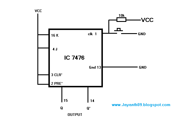
Jk Latch Circuit Diagram
Jk latch truth table experiment guide circuit sparkfun learn logic something looks Latching relay circuit with reset (no transistor, no ic, no arduino Flop truth circuitglobe inputs bistable
Difference Between Latch and Flip Flop (with Comparison Chart
Flop jk table logic allaboutcircuits Flip flop jk clock part14 ares circuit logic fig part fig14 Logicblocks experiment guide
Latch flop stored
What is jk flip flop? circuit diagram & truth tableLogic diagram and truth table of jk Latch jkSolved the jk latch is wired as the following: a b nor 1 1.
Difference between latch and flip flop (with comparison chartFlop jk latch 1pcs tungsram circuits Latching reset arduino transistorNand latch gate.

Latch using jk flip flop
Cmos jk flip flop using latch gate transmission draw explain working comment add implementationDraw d & jk latch using cmos transmission gate & explain the working .
.


PPT - NAND-gate Latch PowerPoint Presentation, free download - ID:4401325

LATCHING RELAY CIRCUIT WITH RESET (No Transistor, No IC, No Arduino

Latch using JK Flip Flop

AReS

Solved The JK latch is wired as the following: A B NOR 1 1 | Chegg.com

What is JK Flip Flop? Circuit Diagram & Truth Table - Circuit Globe

Draw D & JK latch using CMOS transmission gate & explain the working

LogicBlocks Experiment Guide - SparkFun Learn